Product details
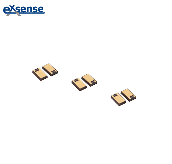

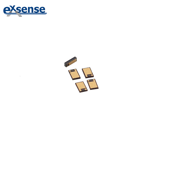
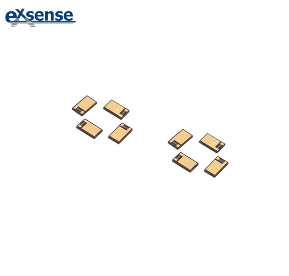
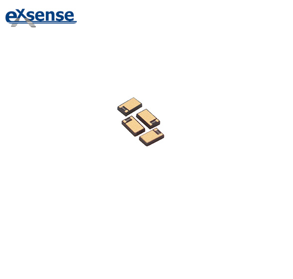
Product category / Single Layer Capacitor
Resistance-capacitance integrated chip capacitor
Guangdong Xinsheng Electronic Technology Co., Ltd.: a resistance-capacitance integrated chip device, which is characterized in that it comprises a ceramic dielectric body, a first electrode set on the lower surface of the ceramic dielectric body, and a resistance-capacitance layer set on the upper surface of the ceramic dielectric body. The resistance-capacitance layer comprises a second electrode, a film resistor and a third electrode, and the second electrode is connected with the first end of the film resistor, The second end of the film resistor is connected with the third electrode, and a channel is arranged between the second electrode and the third electrode, which isolates the second electrode from the third electrode.
- Small size,large capacitance,excellent microwave performance
- Good solderability
- The borders help prevent short circuits(arcing at the chip edges)after die attachment,especially with conductive epoxy. The design also reduces handling damage from tweezers,and facilitates automated pick and place assembly processes.
- The integration of resistance and capacitance improves the comprehensive performance
- One side of the electrode is reserved
- Electrode structure: TaN+Tiw+Au
- Microwave integrated circuit, DC isolation,bypass,impedance matching,etc.
- The design allows the user to match line with or design a custom capacitor for limited circuit dimensions.
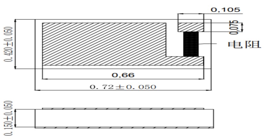
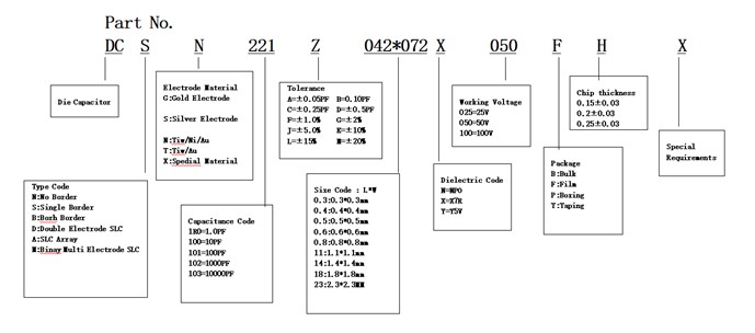
Product Model:DCSN221Z042×072X050F(R201M)
- DC: chip capacitance
- S: Single-sided edge reserved type
- Electrode type N: Ti/W+Au
- Nominal capacity 221:220PF
- Capacity error level Z:+80% – 20%
- Dimension code W * L: 0.42 * 0.72mm
- Temperature characteristic code X: X7R
- Rated working voltage 050:50V
- Packing method F: film
- Special requirements of customers: resistance R=200 Ω ± 20%
| Material code | Dielectric constant(K) | Dielectric loss(DF)@25 ℃ | Insulation resistance(IR)@25 ℃ | Humidity characteristics(TC) | Temperature range | Eiatc model |
| N0 | 5 | <0.15%@1MHz | MΩ | 0±30ppm/ ℃ | -55~+125℃ | COG |
| N1 | 15 | <0.15%@1MHz | MΩ | 0±30ppm/ ℃ | -55~+125℃ | COG |
| N2 | 39 | <0.15%@1MHz | MΩ | 0±30ppm/ ℃ | -55~+125℃ | COG |
| N3 | 90 | <0.25%@1MHz | MΩ | 0±30ppm/ ℃ | -55~+125℃ | COG |
| N5 | 130 | <0.15%@1MHz | MΩ | 0±30ppm/ ℃ | -55~+125℃ | COG |
| N6 | 230 | <0.25%@1MHz | MΩ | -750±120ppm/ ℃ | -55~+125℃ | U2J |
| N4 | 300 | <0.25%@1MHz | MΩ | -900±500ppm/ ℃ | -55~+125℃ | A3L |
| N7 | 700 | <0.25%@1MHz | MΩ | -3300±500ppm/ ℃ | -55~+125℃ | S3L |
| B1 | 3000 | <2.5%@1KHz | MΩ | ±15% | -55~+125℃ | X7R |
| Y0 | 7000 | <3.0%@1KHz | MΩ | +22%/-56% | -30~+85℃ | Y5U |
| Y1 | 9000 | <3.0%@1KHz | MΩ | +22%/-56% | -30~+85℃ | Y5U |
| Y2 | 18000 | <3.0%@1KHz | MΩ | +22%/-82% | -30~+85℃ | Y5V |
| X1 | 20000 | <3.0%@1KHz | MΩ | ±15% | -55~+125℃ | X7R |
| X2 | 30000 | <3.0%@1KHz | MΩ | +22% | -55~+125℃ | X7S |

